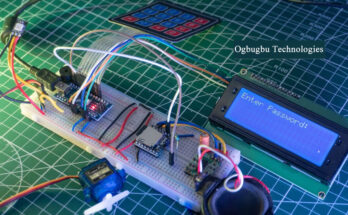
As everyone is aware, security is a top priority. The number of theft cases is rising sharply also. Since everyone is worried about the safety of their homes and lockers, a door lock system that uses a password can help. Only after entering the right password will the door open.
Objective
This project’s major goal is to switch out the conventional door lock system, which uses a mechanical lock and key mechanism, with a password-based system.
Minimal power usage
Easy to understand and apply
Economical
Component Required
Hardware
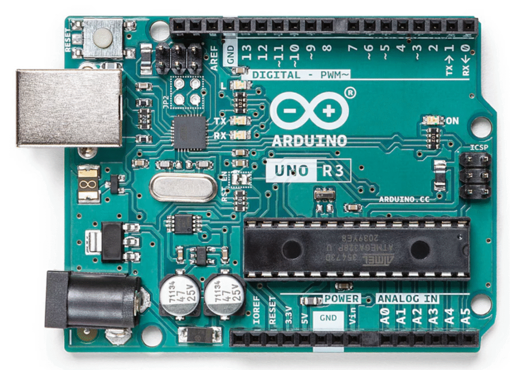
Arduino UNO: The Arduino Uno-board is a 8 bit-microcontroller. It has I/0 pins including both digital and analog pins.
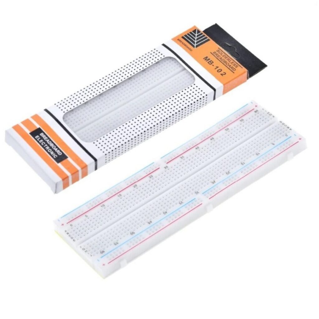
Bread board: It is a rectangular board having mounting holes present everywhere on it in a systematic manner. They are used for creating connections between components. The connections are not permanent and therefore can be removed and placed again.
Jumpers Wires: It is an electrical wire having connector (pin) at each end which is used for connecting the components. There is no need of soldering if one is using the breadboard for making connections between components in their project.

SG-90 Servo Motor: It is small and light weight server motor with large output power. A servo motor can turn 90 degree in either direction.

4*4 Matrix Keypad Membrane: It is used as an input in a project. It has total 16 keys.

Door Latch:

I2C 16×2 LCD Display

Arduino Push Button

Software
- Arduino Software (IDE): It is an open-source Software (IDE) which makes it easy for us to write code and upload it to the Arduino boards. It runs on Windows, Linux etc.
Description
Here in this project called password based door lock system; 4*4 keypad matrix is used to take input. Users have to enter the correct password to unlock the door. When the password is entered by the user, it is compared with the predefined password. If the password entered is correct then the system will open the door latch with the help of servo motor.
Connections
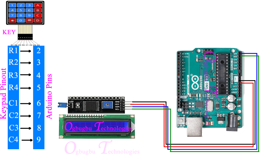
Keypad
Connection Key
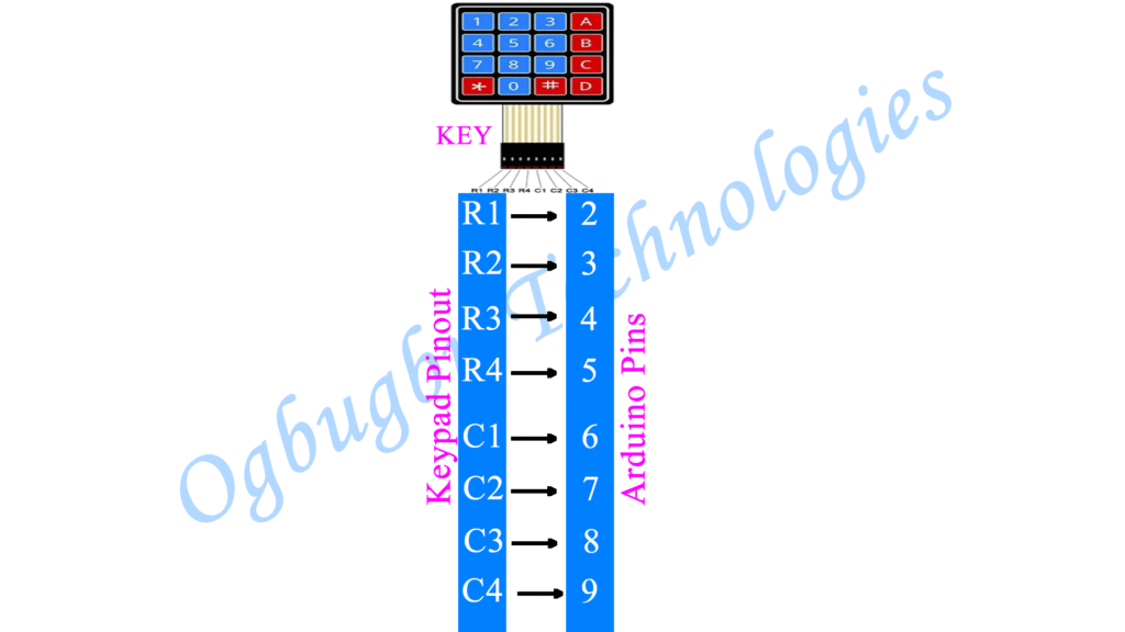
Keypad to Arduino
R1 – 2D pin
R2 – 3D pin
R3 – 4D pin
R4 – 5D pin
C1 – 6D pin
C2 – 7D pin
C3 – 8D pin
C4 – 9D pin
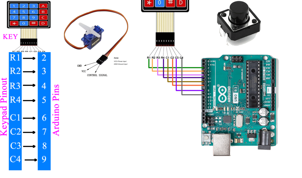
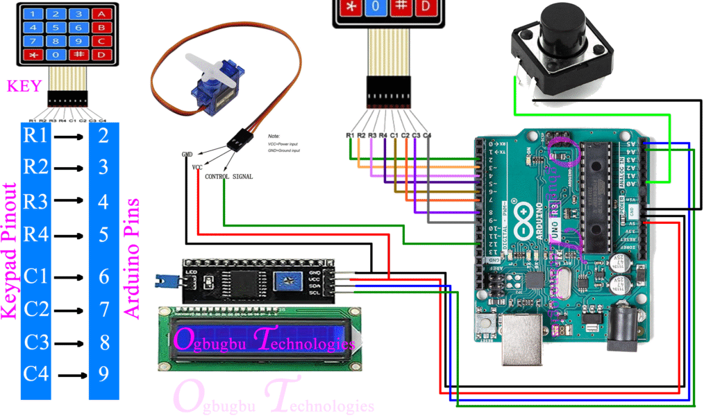
Servo to Arduino
Positive (red) – +5V
Negative (brown) – Ground
Signal (yellow) – 12 pin
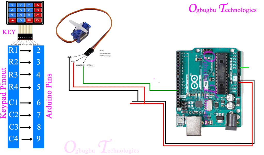
I2C 16×2 LCD Display
Positive (red) – +5V
Negative (black) – Ground
SDA (blue) – A5 pin
SCL (Green) – A4
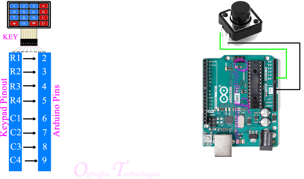
Button to Arduino
Pin1 – A0
Pin2 – Negative (black) – Ground
Complete Circuit Diagram of Project
Video Tutorial of Project
Project Code
#include <Wire.h>
#include <LiquidCrystal_I2C.h>
#include <Keypad.h>
#include <Servo.h>

// I2C LCD setup
LiquidCrystal_I2C lcd(0x27, 16, 2); // Adjust 0x27 to match your I2C address

// Define keypad layout
const byte ROWS = 4; // Four rows
const byte COLS = 4; // Four columns
char keys[ROWS][COLS] = {
  {'1', '2', '3', 'A'},
  {'4', '5', '6', 'B'},
  {'7', '8', '9', 'C'},
  {'*', '0', '#', 'D'}
};
byte rowPins[ROWS] = {9, 8, 7, 6}; // Connect to the row pins of the keypad
byte colPins[COLS] = {5, 4, 3, 2}; // Connect to the column pins of the keypad

Keypad keypad = Keypad(makeKeymap(keys), rowPins, colPins, ROWS, COLS);

// Password setup
String password = "1234"; // Set your password
String inputCode = "";    // To store the entered code
int accessCount = 0;      // Counter for access state (locked/unlocked)

// Servo setup
Servo myServo;            // Create a servo object
int lockPosition = 0;     // Servo position for locked state
int unlockPosition = 90;  // Servo position for unlocked state

// Push button setup
const int buttonPin = A0; // Push button connected to pin A0
bool buttonState = LOW;   // Current state of the button
bool lastButtonState = LOW;

// WTV020 MP3 setup
#define MP3_RX 10  // RX pin for WTV020
#define MP3_TX 11  // TX pin for WTV020

void playSound(int trackNumber) {
  Serial.write(0x7E);      // Start byte
  Serial.write(0x04);      // Length of command
  Serial.write(0x03);      // Play track command
  Serial.write(trackNumber); // Track number
  Serial.write(0xEF);      // End byte
}

void setup() {
  // Initialize serial communication
  Serial.begin(9600);

  // Initialize LCD
  lcd.init();
  lcd.backlight();
  lcd.setCursor(0, 0);
  lcd.print("Enter Password:");

  // Initialize servo
  myServo.attach(12); // Servo connected to pin 12
  myServo.write(lockPosition); // Start in locked position

  // Initialize MP3 module
  pinMode(MP3_RX, OUTPUT);
  pinMode(MP3_TX, INPUT);
  Serial.write(0xFF); // Wake up the MP3 module
  delay(500);

  // Initialize push button
  pinMode(buttonPin, INPUT_PULLUP); // Use internal pull-up resistor
}

void lockAction() {
  myServo.write(lockPosition); // Move servo to lock position
  playSound(1);                // Play lock sound (Track 1)
  lcd.setCursor(0, 1);
  lcd.print("Locked          ");
  delay(2000);
}

void unlockAction() {
  myServo.write(unlockPosition); // Move servo to unlock position
  playSound(2);                  // Play unlock sound (Track 2)
  lcd.setCursor(0, 1);
  lcd.print("Unlocked        ");
  delay(2000);
}

void wrongPassword() {
  playSound(3);                  // Play wrong password sound (Track 3)
  lcd.setCursor(0, 1);
  lcd.print("Access Denied   ");
  delay(2000);
}

void loop() {
  // Check keypad input
  char key = keypad.getKey(); // Get the pressed key

  if (key) {
    lcd.setCursor(0, 1);
    lcd.print("                "); // Clear the second line
    lcd.setCursor(0, 1);
    lcd.print("Key: ");
    lcd.print(key);

    if (key == '*') { // Reset the input
      inputCode = "";
      lcd.setCursor(0, 1);
      lcd.print("Reset           ");
    } else if (key == '#') { // Submit the code
      if (inputCode == password) {
        if (accessCount == 0) {
          unlockAction();   // Unlock
          accessCount = 1;  // Update state
        } else {
          lockAction();     // Lock
          accessCount = 0;  // Update state
        }
      } else {
        wrongPassword();    // Deny access
      }
      inputCode = ""; // Clear the input after checking
    } else {
      inputCode += key; // Append the pressed key to inputCode
    }
  }

  // Check push button input
  buttonState = digitalRead(buttonPin); // Read the button state

  // Detect button press (rising edge)
  if (buttonState == HIGH && lastButtonState == LOW) {
    delay(50); // Debounce delay
    if (accessCount == 0) {
      unlockAction(); // Unlock if currently locked
      accessCount = 1;
    } else {
      lockAction(); // Lock if currently unlocked
      accessCount = 0;
    }
  }
  lastButtonState = buttonState; // Update button state
}
