Building your own custom electronic components is one of the most rewarding aspects of DIY electronics. Instead of using a standard off-the-shelf module, you can create a unique, oversized seven-segment display by combining individual LEDs, a custom circuit board (or foam/cardboard base), and a sleek, protective 3D-printed case. This article guides you through the process, resulting in a large, visually striking display perfect for custom clocks, scoreboards, or status indicators.
1. 💡 The Custom LED Array
The core of this project is the seven-segment layout, but built from scratch using large individual LEDs.
- Design: As shown in the image, the display uses 14 individual LEDs to form the segments of two digits, plus an additional LED for the decimal point (or in the example, a separate indicator light).
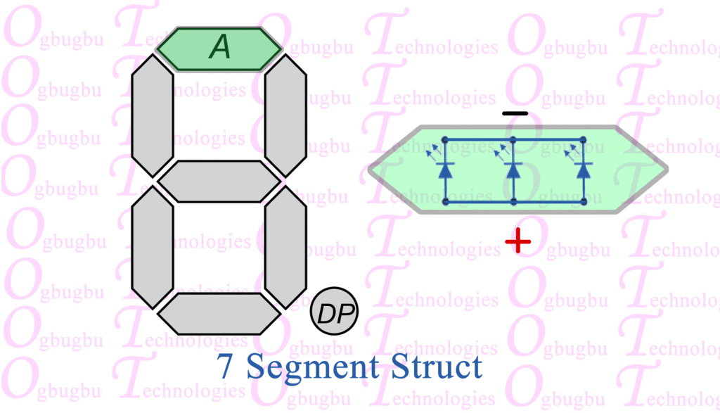
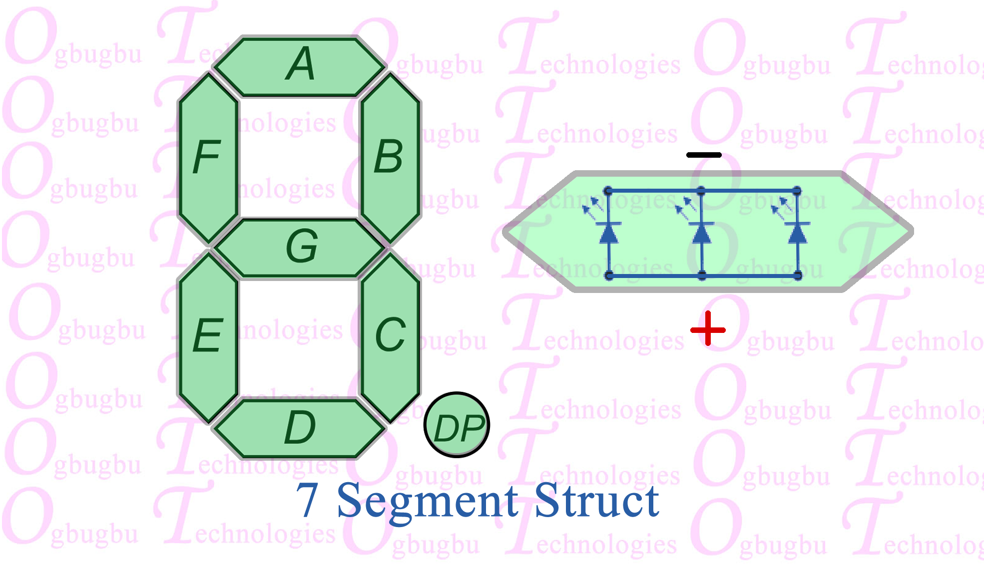
- Segment Mapping: Each digit requires seven LEDs arranged in the familiar figure-eight pattern. You must meticulously wire these LEDs to form seven distinct segments (labeled ‘a’ through ‘g’).
- Base Construction: The LEDs can be mounted and wired on a small piece of foam or cardboard to hold their positions and provide a structure for soldering the wires. Ensure you maintain polarity (all cathodes connected together for a Common Cathode design, or all anodes for Common Anode).
- Current Limiting: Since these are large LEDs, you must use a current-limiting resistor (typically $220\ \Omega$ to $1\ \text{k}\Omega$, depending on the LEDs) on each segment’s wire before connecting it to the Arduino.
Video of Design Process
Design Process
Segment A
Segment B
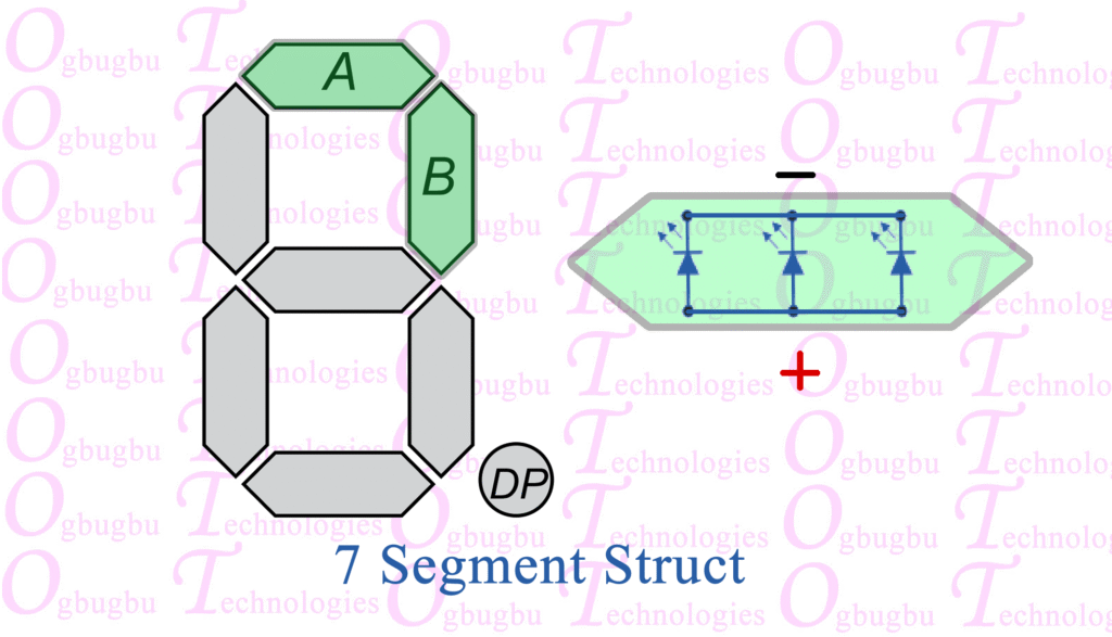
Segment C
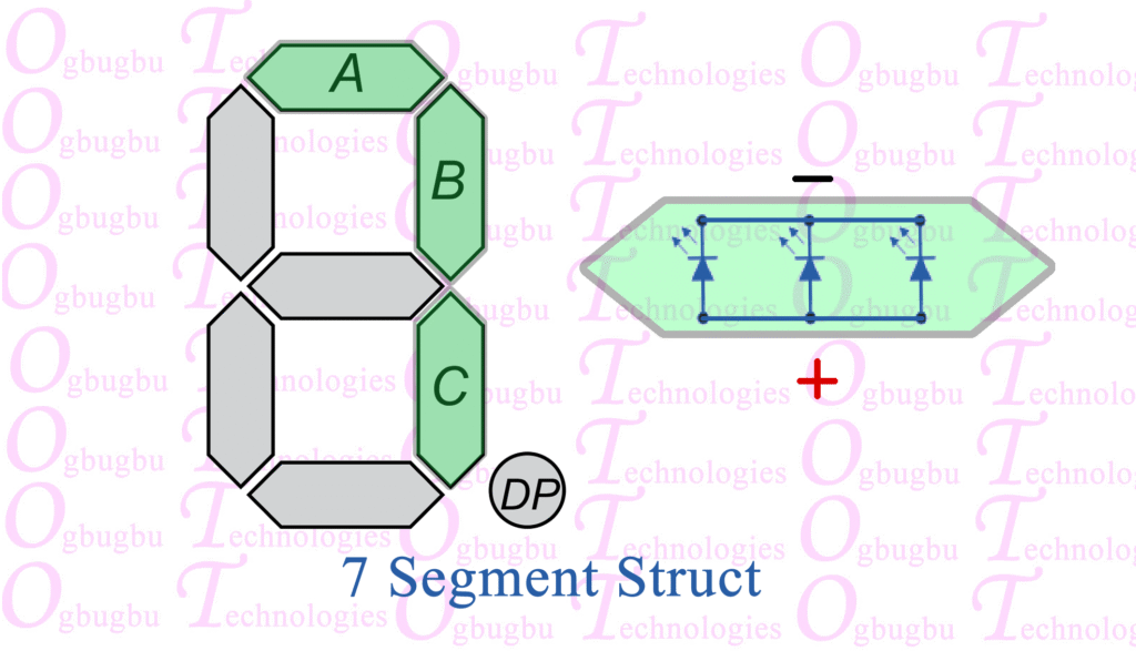
Segment D
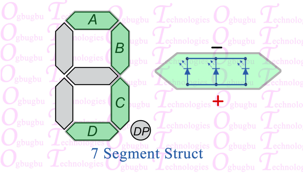
Segment E
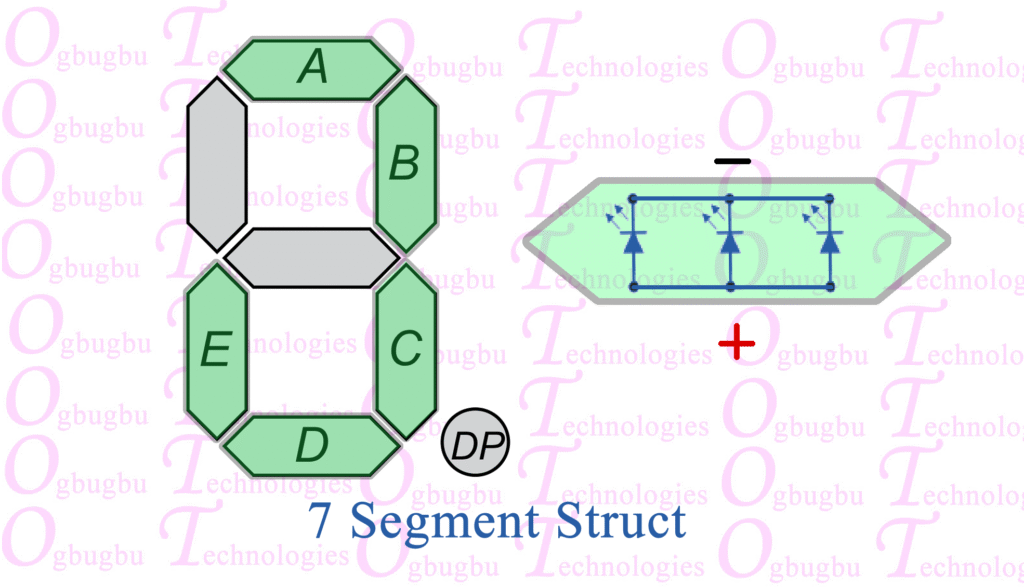
Segment F
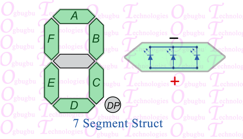
Segment G
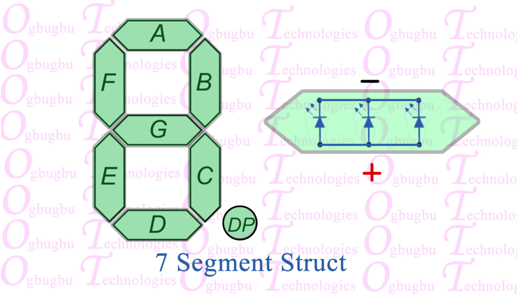
Segment DP
2. 🖨️ Designing and 3D Printing the Case
The 3D-printed case gives your DIY project a professional, polished look and serves as a crucial mechanical component.
- CAD Design: Use a 3D modeling program (like TinkerCAD, Fusion 360, or Blender) to design a rectangular housing.
- Compartments: The design needs seven distinct troughs or cavities arranged to match the seven segments of a digit. These cavities will channel the light from the individual LEDs to form a clear number shape.
- Diffusion: A thin, translucent layer (or a separate diffuser print) can be placed over the segments to spread the light evenly and reduce harsh hotspots from the individual LEDs.
- Mounting: Include space in the back to perfectly fit your wired LED array.
- Printing: Print the case using your preferred material (PLA is common and easy). The color choice is up to you, but a dark color will make the segments contrast better when they are off, while a translucent material can enhance the glow.
3. 🧠 Interfacing with the Arduino Nano
The control logic is handled by a small microcontroller, such as an Arduino Nano, which is compact and powerful enough for this task.
- Connection Board: As seen in the first image, the Arduino Nano can be mounted onto a small screw terminal breakout board. This makes it easy to attach the numerous wires from the seven-segment display securely.
- Wiring Scheme: Connect each of the seven segment wires (plus the decimal point, if used) from your display, through their respective current-limiting resistors, to separate digital output pins on the Arduino Nano.
- Power: Ensure the Arduino Nano and the display’s common wire are correctly grounded (or connected to $5\text{V}$, depending on your display type).
4. 💻 Example Arduino Code (Common Cathode)
The code for a custom large-segment display is the same as for an off-the-shelf one—it’s all about mapping the pin states to form the numbers. Assuming your custom array is Common Cathode (meaning HIGH turns segments ON):
// Define the pins connected to segments a through g
const int segPins[] = {2, 3, 4, 5, 6, 7, 8};

// Lookup table for digits 0-9: {a, b, c, d, e, f, g}
// 1 = ON (HIGH), 0 = OFF (LOW)
const byte digitPatterns[][7] = {
  {1, 1, 1, 1, 1, 1, 0}, // 0
  {0, 1, 1, 0, 0, 0, 0}, // 1
  // ... continue for all digits 2 through 9
};

void displayNumber(int num) {
  // Sets the state of all 7 pins based on the pattern
  for (int i = 0; i < 7; i++) {
    digitalWrite(segPins[i], digitPatterns[num][i]);
  }
}

void setup() {
  // Set all segment pins as OUTPUTs
  for (int pin : segPins) {
    pinMode(pin, OUTPUT);
  }
}

void loop() {
  // Example: Display '2' and hold it
  displayNumber(2);
  delay(5000);

  // Example: Display '5' and hold it
  displayNumber(5);
  delay(5000);
}
