Passive Infrared (PIR) sensors are an inexpensive and popular way to detect motion, often found in home security systems and automatic lighting. This blog post will guide you through connecting a PIR sensor to an Arduino and writing the code to detect motion.
What You’ll Need:
- Arduino Uno (or compatible board)
- PIR Motion Sensor (HC-SR501 is a common model)
- Jumper Wires
- Breadboard (optional, but recommended for cleaner connections)
- USB Cable for Arduino
Understanding the PIR Sensor
A PIR sensor has three pins:
- VCC: Connects to 5V on Arduino
- OUT (or SIG): Connects to a digital pin on Arduino (this is where the motion detection signal comes from)
- GND: Connects to Ground on Arduino
Most PIR sensors also have two potentiometers:
- Sensitivity: Adjusts the detection range.
- Time Delay: Sets how long the output pin stays HIGH after motion is detected.

TIP: Ask Gemini to refine images
With image generation in Gemini, your imagination is the limit. If what you see doesn’t quite match what you had in mind, try adding more details to the prompt. The more specific you are, the better Gemini can create images that reflect your vision.
Detect Motion with PIR Sensor and Arduino
Passive Infrared (PIR) sensors are an inexpensive and popular way to detect motion, often found in home security systems and automatic lighting. This blog post will guide you through connecting a PIR sensor to an Arduino and writing the code to detect motion.
What You’ll Need:
- Arduino Uno (or compatible board)
- PIR Motion Sensor (HC-SR501 is a common model)
- Jumper Wires
- Breadboard (optional, but recommended for cleaner connections)
- USB Cable for Arduino
Understanding the PIR Sensor
A PIR sensor has three pins:
- VCC: Connects to 5V on Arduino
- OUT (or SIG): Connects to a digital pin on Arduino (this is where the motion detection signal comes from)
- GND: Connects to Ground on Arduino
Most PIR sensors also have two potentiometers:
- Sensitivity: Adjusts the detection range.
- Time Delay: Sets how long the output pin stays HIGH after motion is detected.
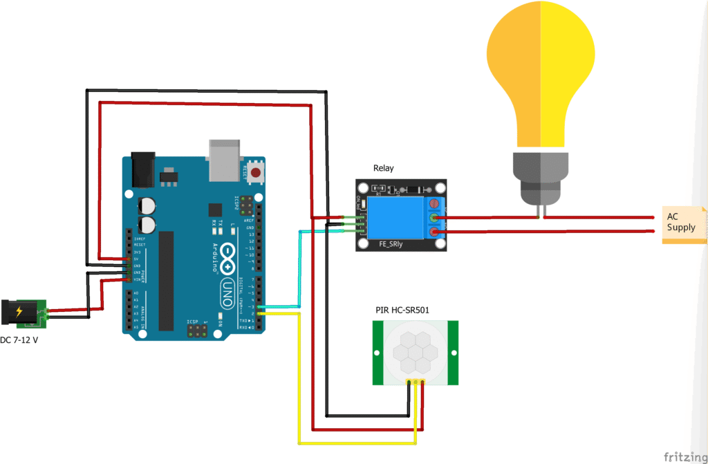
Connection Diagram:
Follow this diagram to connect your PIR sensor to the Arduino:
- Connect the VCC pin of the PIR sensor to the 5V pin on your Arduino.
- Connect the GND pin of the PIR sensor to the GND pin on your Arduino.
- Connect the OUT (or SIG) pin of the PIR sensor to Digital Pin 2 on your Arduino.
Arduino Code:
Now, let’s upload the code to your Arduino to read the PIR sensor’s output.
#define SENSOR_PIN 2
#define RELAY_PIN 3

void setup()
{
  pinMode(RELAY_PIN, OUTPUT);
  pinMode(SENSOR_PIN, INPUT);
  //Serial.begin(9600);
}

void loop()
{
  //If object movement is detected then the sensor value will be 1 else the value will be 0
  int sensorValue = digitalRead(SENSOR_PIN);
  //Serial.println(sensorValue);
  if (sensorValue == HIGH)
  {
    digitalWrite(RELAY_PIN, LOW);  //Relay is low level triggered relay so we need to write LOW to switch on the light
  }
  else
  {
    digitalWrite(RELAY_PIN, HIGH);
  }
}
How the Code Works:
const int pirPin = 2;: This line defines which digital pin the PIR sensor’s output is connected to.Serial.begin(9600);: This initializes the serial monitor, allowing your Arduino to send messages to your computer.pinMode(pirPin, INPUT);: This sets Digital Pin 2 as an input, as we are reading data from the PIR sensor.digitalRead(pirPin);: In theloop(), this function reads the current state of the PIR sensor pin.- If motion is detected, the
pirPinwill go HIGH (5V). - If no motion is detected, the
pirPinwill remain LOW (0V).
- If motion is detected, the
if (pirState == HIGH): This checks if the sensor has detected motion. If it has, “Motion Detected!” is printed to the serial monitor. Otherwise, “No Motion” is printed.delay(500);: This adds a 500-millisecond delay between readings, preventing the serial monitor from being flooded with messages.
Testing Your Setup:
- Connect your Arduino to your computer via the USB cable.
- Open the Arduino IDE, paste the code, and upload it to your Arduino board.
- Open the Serial Monitor (Tools > Serial Monitor) in the Arduino IDE.
- Once the “PIR Sensor Ready!” message appears, wave your hand in front of the PIR sensor. You should see “Motion Detected!” printed in the serial monitor. When you stop moving, it will eventually revert to “No Motion”.
Further Enhancements:
- Add an LED: Connect an LED to another digital pin (e.g., pin 13) and make it light up when motion is detected.
- Sound Alarm: Integrate a buzzer to create an audible alarm when motion is sensed.
- Home Automation: Connect it to a relay to control lights or other appliances.
You’ve now successfully set up a PIR motion sensor with your Arduino! This basic setup can be the foundation for many exciting home automation and security projects.


