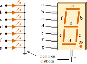
A seven-segment display is a common electronic component used to display decimal numerals (0-9) and a few characters. It’s essentially made up of seven individual LEDs, or segments, arranged in a figure-eight pattern, plus an optional eighth LED for a decimal point (DP). Learning to interface one with an Arduino is a fundamental skill in electronics and programming.
Understanding the 7-Segment Display Types
There are two main types of seven-segment displays, distinguished by how the internal LEDs are wired:
| Type | Common Pin Connection | Logic to Turn Segment ON |
| Common Cathode (CC) | All LED Cathodes are tied together to a common ground (GND). | Apply a HIGH signal (5V) to the segment’s anode pin. |
| Common Anode (CA) | All LED Anodes are tied together to a common positive voltage (VCC, typically 5V). | Apply a LOW signal (GND) to the segment’s cathode pin. |
Note: You must use the correct wiring and code logic for your display type. Failure to do so can result in the display not working or, in rare cases, damage.
🔌 Circuit Diagram and Wiring (Common Cathode Example)
For this example, we’ll use a Common Cathode (CC) display and an Arduino Uno.
Components Needed:
- Arduino Uno
- Single Digit Common Cathode 7-Segment Display
- 8 x 220 Ohm resistors (one for each segment, including the DP, to limit current)
- Breadboard
- Jumper Wires
Wiring Instructions:

| 7-Segment Pin | Function | Connection |
| Common | Common Cathode | Arduino GND |
| A | Top horizontal segment | $\rightarrow$ 220 $\Omega$ Resistor $\rightarrow$ Arduino Digital Pin 2 |
| B | Top right vertical segment | $\rightarrow$ 220 $\Omega$ Resistor $\rightarrow$ Arduino Digital Pin 3 |
| C | Bottom right vertical segment | $\rightarrow$ 220 $\Omega$ Resistor $\rightarrow$ Arduino Digital Pin 4 |
| D | Bottom horizontal segment | $\rightarrow$ 220 $\Omega$ Resistor $\rightarrow$ Arduino Digital Pin 5 |
| E | Bottom left vertical segment | $\rightarrow$ 220 $\Omega$ Resistor $\rightarrow$ Arduino Digital Pin 6 |
| F | Top left vertical segment | $\rightarrow$ 220 $\Omega$ Resistor $\rightarrow$ Arduino Digital Pin 7 |
| G | Middle horizontal segment | $\rightarrow$ 220 $\Omega$ Resistor $\rightarrow$ Arduino Digital Pin 8 |
| DP | Decimal Point | $\rightarrow$ 220 $\Omega$ Resistor $\rightarrow$ Arduino Digital Pin 9 |
💻 Arduino Code (Common Cathode)
This code is designed to display the numbers 0 through 9 sequentially on a Common Cathode display.
// Define the Arduino pins connected to the segments (a, b, c, d, e, f, g) and DP
// Matching the wiring table: a=2, b=3, c=4, d=5, e=6, f=7, g=8, DP=9
const int segmentPins[] = {2, 3, 4, 5, 6, 7, 8}; // DP is excluded for simplicity

// Segment patterns for numbers 0 to 9 for a COMMON CATHODE display
// Array order corresponds to segmentPins[]: {a, b, c, d, e, f, g}
// 1 = ON (HIGH), 0 = OFF (LOW)
const byte digitPatterns[][7] = {
  // a, b, c, d, e, f, g
  {1, 1, 1, 1, 1, 1, 0}, // 0
  {0, 1, 1, 0, 0, 0, 0}, // 1
  {1, 1, 0, 1, 1, 0, 1}, // 2
  {1, 1, 1, 1, 0, 0, 1}, // 3
  {0, 1, 1, 0, 0, 1, 1}, // 4
  {1, 0, 1, 1, 0, 1, 1}, // 5
  {1, 0, 1, 1, 1, 1, 1}, // 6
  {1, 1, 1, 0, 0, 0, 0}, // 7
  {1, 1, 1, 1, 1, 1, 1}, // 8
  {1, 1, 1, 1, 0, 1, 1}  // 9
};

// Function to display a number from 0 to 9
void displayNumber(int num) {
  if (num >= 0 && num <= 9) {
    // Loop through all 7 segments
    for (int i = 0; i < 7; i++) {
      // Write the corresponding pin HIGH (ON) or LOW (OFF)
      digitalWrite(segmentPins[i], digitPatterns[num][i]);
    }
  }
}

void setup() {
  // Set all segment pins as OUTPUTs
  for (int i = 0; i < 7; i++) {
    pinMode(segmentPins[i], OUTPUT);
  }
}

void loop() {
  // Loop through numbers 0 to 9
  for (int i = 0; i < 10; i++) {
    displayNumber(i); // Display the current number
    delay(1000);      // Wait for 1 second
  }
}

/*
* If you were using a Common Anode display, the digitPatterns would be inverted
* (0 = ON, 1 = OFF), and the common pin would connect to 5V.
*/


