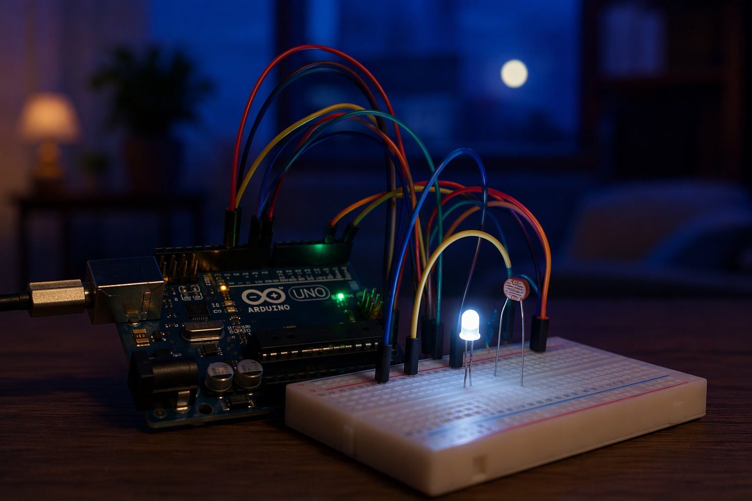
Street lights that switch themselves on at dusk use the same component you’ll wire today: an LDR (light dependent resistor). Its resistance drops as light increases, and combined with a fixed resistor it forms a voltage divider the Arduino can read with analogRead(). In this project the Arduino reads the ambient light level and fades a white LED on as the room gets dark, a real night light.
This is one of the best beginner builds for understanding analog sensors, thresholds and PWM dimming, three ideas you’ll reuse constantly.
Components Required
- Arduino Uno (or Nano)
- LDR photoresistor (GL5528 or similar)
- 10k resistor
- White LED
- 220Ω resistor
- Breadboard and jumper wires
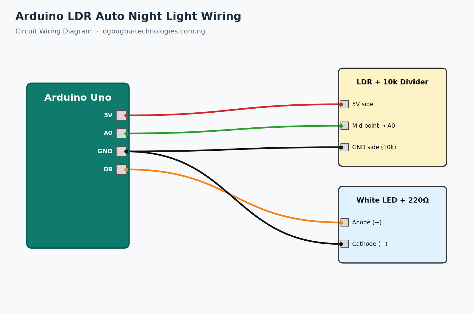
Circuit Diagram and Wiring
The Code (Arduino IDE)
/*
 * Arduino LDR Automatic Night Light
 * Ogbugbu Technologies - ogbugbu-technologies.com.ng/
 */
#define LDR_PIN A0
#define LED_PIN 9        // PWM pin for smooth dimming

const int DARK_THRESHOLD  = 300;   // below this = dark (calibrate!)
const int LIGHT_THRESHOLD = 700;   // above this = bright room

void setup() {
  Serial.begin(9600);
  pinMode(LED_PIN, OUTPUT);
}

void loop() {
  int lightLevel = analogRead(LDR_PIN);   // 0 = dark, 1023 = bright
  Serial.print("Light level: ");
  Serial.println(lightLevel);

  // Map darkness to LED brightness: darker room -> brighter LED
  int brightness = map(lightLevel, DARK_THRESHOLD, LIGHT_THRESHOLD, 255, 0);
  brightness = constrain(brightness, 0, 255);

  analogWrite(LED_PIN, brightness);
  delay(200);
}
How the Code Works
The LDR and the 10k resistor form a voltage divider. In bright light the LDR resistance is low, pulling A0 towards 5V (high reading); in darkness its resistance rises to megaohms, so the 10k resistor pulls A0 towards ground (low reading). The exact raw values depend on your room and resistor, which is why the first step is to open the Serial Monitor and note the readings with the room bright and with the LDR covered.
Instead of a harsh on/off switch, map() converts the light range into a smooth 0–255 PWM value, so the LED brightens gradually as evening falls. Using analogWrite() on pin D9 (a PWM pin) dims the LED without any extra components. Add two fixed thresholds with hysteresis if you prefer a simple on/off behaviour that never flickers at dusk.
Testing and Troubleshooting
Cover the LDR with your hand: the LED should glow. Shine your phone torch at it: the LED should fade out. If nothing changes, you’ve probably wired A0 to the wrong side of the divider. A0 must connect to the junction between the LDR and the 10k resistor. If the LED is inverted (bright in daylight), swap the 255 and 0 in the map() call.
Conclusion
You’ve just built the sensing half of every automatic lighting product on the market. Combine this with the relay from our PIR tutorial to switch a real lamp, or add several LEDs for a brighter bedside night light.
Found this tutorial helpful? Share it with a fellow maker and check out more builds on Ogbugbu Technologies!